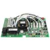
Balboa BP2100G1 PCB
£405.92 Inc VAT
15 in stock
⚡ Balboa BP2100G1 Spa Circuit Board – Advanced Control PCB for BP2100 Systems
Restore complete control to your hot tub with this precision-engineered replacement board from Balboa Water Group.
📋 Product Overview
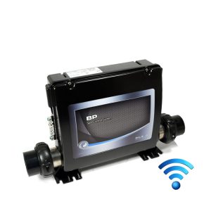
The Balboa BP2100G1 PCB is the intelligent heart of the BP2100 spa control system, manufactured by Balboa Water Group – the industry leader in hot tub electronics. This advanced printed circuit board delivers comprehensive management of your spa’s essential functions, including multiple pump outputs, heater control, lighting, ozone generation, and entertainment systems.
Designed as a direct replacement for BP2100 control boxes, this PCB utilises Balboa’s renowned M7 temperature sensing technology for precise temperature regulation and superior dry-fire protection. The board supports up to three pumps, a circulation pump, blower, and is fully compatible with Balboa’s TP series topside control panels. WiFi-ready connectivity allows smartphone control when paired with a compatible WiFi transceiver module, bringing modern convenience to your spa experience.
Whether you’re replacing a faulty board or restoring an older spa system, the BP2100G1 PCB delivers the reliability and functionality that spa owners expect from genuine Balboa equipment.
⭐ Key Features
✅ 230V/50Hz European Specification – Designed specifically for UK and European electrical systems with full CE compliance
✅ 3kW Heater Support – Controls heaters up to 3.0kW for efficient water heating with built-in dry-fire protection
✅ Triple Pump Capability – Supports up to three pumps (Pump 1, Pump 2, and Pump 3) with single or dual-speed configurations
✅ Circulation Pump Output – Dedicated 2A circuit for continuous low-flow circulation in programmable filtration setups
✅ M7 Sensor Technology – Balboa’s patented dual-sensor system eliminates the need for pressure or flow switches
✅ 18 Configurable Setups – Versatile DIP switch programming accommodates virtually any spa configuration
✅ WiFi Ready – Compatible with Balboa WiFi transceiver for smartphone control via iOS and Android apps
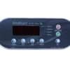
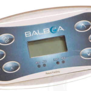
✅ TP Series Panel Compatible – Works with TP600CE, TP800, and TP900 topside control panels (TP400 also compatible per Balboa documentation)
✅ Integrated Entertainment – 5A always-on A/V output for radio, TV, or audio system connections
✅ Built-In Diagnostics – Comprehensive error code system and fault logging for simplified troubleshooting
✅ Ozone Generator Support – 0.5A ozone output for enhanced water sanitation
✅ CE Certified – Meets European safety and electromagnetic compatibility standards
🔧 Technical Specifications
| Specification | Value |
|---|---|
| Part Numbers | 56389-01 (800 Incoloy), 56390-01 (8250 Incoloy), 56391-01 (Titanium) |
| Board Type | Main Control PCB |
| Base PCBA | 56392-01 |
| Bare Board Reference | 24082_E |
| Input Voltage | 230VAC |
| Frequency | 50Hz |
| Single Service | 230VAC, 50Hz, 1φ, 32A (Circuit Breaker: 40A max) |
| Three-Phase Service | 400VAC, 50Hz, 3φ, 16A per phase (Circuit Breaker: 20A max per phase) |
| Heater Output | Up to 3.0kW @ 240VAC |
| Pump 1 Output | 230VAC, 2-Speed, 12A max |
| Pump 2 Output | 230VAC, 2-Speed, 12A max |
| Pump 3 Output | 230VAC, 2-Speed, 12A max |
| Circulation Pump | 230VAC, 1-Speed, 2A max |
| Blower Output | 230VAC, 1-Speed, 4A max |
| Ozone Output | 230VAC, 0.5A max |
| Light Output | 10VAC, 1A max (240-minute timer) |
| A/V Output | 230VAC, 5A max (Always on) |
| Sensor Inputs | Dual M7 temperature sensors (Sensor A & Sensor B) |
| Pump Timers | 15-minute auto-shutoff |
| Setup Configurations | 18 programmable setups |
| Certifications | CE |
🔗 Compatibility Guide
Compatible Topside Control Panels
| Panel Model | Minimum Version | Part Number (With Overlay) | Part Number (Without Overlay) |
|---|---|---|---|
| TP600CE | Version 2.3 or later | 50336 | 50015 |
| TP800 | Version 1.2 or later | 50261 | 50204 |
| TP900 | Version 1.2 or later | 50262 | 55994 |
| TP400 | Compatible (see manual) | Refer to Balboa documentation | Refer to Balboa documentation |
⚠️ Important: TP600 (non-CE version) should NOT be used with this board.
Compatible Control Box
| Control Box | Compatibility |
|---|---|
| BP2100 | ✅ Direct replacement |
| BP2100G1 Complete System | ✅ Original equipment |
Replaces Part Numbers
| Part Number | Description |
|---|---|
| 56389-01 | BP2100G1 PCB (800 Incoloy heater) |
| 56390-01 | BP2100G1 PCB (8250 Incoloy heater) |
| 56391-01 | BP2100G1 PCB (Titanium heater) |
⚠️ Always verify your existing board’s part number before ordering. This board is specifically designed for BP2100 control boxes and should not be fitted to other systems.
🎛️ Board Functions & Controls
Pump Control
| Output | Function | Rating | Timer |
|---|---|---|---|
| Pump 1 | Main jet pump (2-speed) | 12A max | 15 minutes |
| Pump 2 | Secondary jets (configurable) | 12A max | 15 minutes |
| Pump 3 | Additional jets (configurable) | 12A max | 15 minutes |
| Circ Pump | 24hr circulation (setups 7-14, 16, 17) | 2A max | Programmable |
Heater Control
| Feature | Specification |
|---|---|
| Heater Type | Electric element (Incoloy or Titanium) |
| Maximum Output | 3.0kW @ 240VAC |
| Temperature Range | 80°F – 104°F / 27°C – 40°C (High Range) |
| Hi-Limit Protection | Built-in sensor protection |
| Dry-Fire Protection | M7 dual-sensor technology |
| Cooldown Period | 1 minute (electric) / 5 minutes (gas) |
Additional Controls
| Function | Capability |
|---|---|
| Lighting | 10VAC, 1A max, 240-minute timer |
| Ozone | 230VAC, 0.5A, slaved to circulation or independent |
| Blower | 230VAC, 4A max, 15-minute timer |
| A/V | 230VAC, 5A, always-on for entertainment systems |
| WiFi | Compatible with Balboa WiFi transceiver module |
| Auxiliary Panels | Supports AX10, AX20, AX40 auxiliary controls |
Setup Configuration Reference
| Setup | Circ Pump | Pump 1 | Pump 2 | Pump 3 | Blower |
|---|---|---|---|---|---|
| 1 | None | 2-Speed | 2-Speed | 2-Speed | None |
| 2 | None | 2-Speed | 2-Speed | 1-Speed | None |
| 3 | None | 2-Speed | 2-Speed | None | 1-Speed |
| 4 | None | 2-Speed | 2-Speed | None | None |
| 5 | None | 2-Speed | 1-Speed | 1-Speed | 1-Speed |
| 6 | None | 2-Speed | 1-Speed | 1-Speed | None |
| 7 | Prog. Filtration | 2-Speed | 2-Speed | 2-Speed | None |
| 8 | Prog. Filtration | 2-Speed | 2-Speed | 1-Speed | None |
| 9 | Prog. Filtration | 2-Speed | 2-Speed | None | 1-Speed |
| 10 | Prog. Filtration | 2-Speed | 2-Speed | None | None |
| 11 | Prog. Filtration | 2-Speed | 1-Speed | 1-Speed | 1-Speed |
| 12 | Prog. Filtration | 1-Speed | 1-Speed | 1-Speed | 1-Speed |
| 13 | Prog. Filtration | 2-Speed | 1-Speed | 1-Speed | None |
| 14 | Prog. Filtration | 1-Speed | 1-Speed | 1-Speed | None |
| 15 | None | 2-Speed | 2-Speed | 1-Speed | 1-Speed |
| 16 | Prog. Filtration | 2-Speed | 2-Speed | 1-Speed | 1-Speed |
| 17 | Prog. Filtration | 1-Speed | 1-Speed | None | 1-Speed |
| 18 | None | 2-Speed | 1-Speed | None | 1-Speed |
💡 Note: Setups 5, 11, 12, 15, and 16 require the BP2X-WIRE KIT (PN 30893). Setups 15 and 16 also require a fused adapter for blower output.
⚙️ DIP Switch Configuration
Switch Bank S1 Functions
| Switch | OFF Position | ON Position |
|---|---|---|
| A1 | Normal operation | Test Mode (Service use only) |
| A2 | No additional pumps with heater | Add 1 high-speed pump with heater |
| A3 | No additional pumps with heater | Add 2 high-speed pumps with heater |
| A4 | No additional pumps with heater | Add 4 high-speed pumps with heater |
| A5 | Special Amperage Rule A | Special Amperage Rule B |
| A6 | Store settings | Memory reset (use during power-up) |
| A7 | 1-minute heater cooldown (electric) | 5-minute heater cooldown (gas) |
| A8-A10 | Not assigned | Not assigned |
⚠️ Switch A6 should be set to OFF upon final installation.
🛠️ Installation Requirements
⚠️ IMPORTANT: All electrical installation must be carried out by a qualified electrician in accordance with BS 7671 (IET Wiring Regulations) and local building regulations.
Pre-Installation Checklist
- [ ] Verify the part number matches your existing board or is a compatible replacement
- [ ] Disconnect all power at the main breaker and RCD
- [ ] Photograph all existing wiring connections before removal
- [ ] Allow capacitors to discharge (wait a minimum of 5 minutes)
- [ ] Verify water supply valves are closed
Electrical Requirements
| Requirement | Specification |
|---|---|
| Supply Voltage | 230VAC, 50Hz |
| Single-Phase Service | 32A minimum circuit breaker |
| Three-Phase Service | 16A per phase minimum |
| RCD Protection | Required (30mA Type A or AC) |
| Earth Connection | Mandatory – use copper conductors only |
| Conductor Rating | Minimum 90°C rated, sized for 60°C ampacity |
| Terminal Torque | 27-30 in. lbs (31.1-34.5 kg cm) for TB1 |
Fuse Specifications
| Fuse | Rating | Function |
|---|---|---|
| F2 | 10A 250VAC | Ozonator and Circulation Pump |
| F3 | 0.125A Slo-Blo | Transformer Input |
| F4 | 3A Slo-Blo | Spa Light |
| F6 | 30A | Pump 1 and A/V |
| F7 | 10A | Blower (jumped for Pump 2) |
| F8 | 30A | Floating output (typically Pump 2/Blower) |
| F1 (Expander) | 30A | Pump 2, Pump 3, or additional outputs |
Key Connection Points
| Connector | Function |
|---|---|
| TB1 | Main power input terminal block |
| J9 | Pump 1 (2-speed) |
| J14 | Auxiliary output (Pump 2/Blower) |
| J15 | Spa Light (10VAC) |
| J21 | Circulation Pump |
| J32 | Ozone Generator |
| J33 | A/V Audio |
| J34/J35 | Main Topside Panel |
| J5/J8 | Auxiliary Panels |
| J40 | IR/RF Receiver |
| Sensor A/B | M7 Temperature Sensors |
💡 Tip: Label or photograph all connections before removing the old board. When reinstalling, torque board mounting screws to 8-10 in. lbs – do not overtighten.
⚠️ Safety Warnings
Electrical Safety
⚠️ DANGER: Risk of Electric Shock! ALWAYS disconnect power at the main breaker before any work on the control system.
⚠️ All electrical work must be performed by a qualified electrician and must conform to BS 7671, IET Wiring Regulations, and all local codes.
⚠️ Do not permit any electrical appliance such as a light, telephone, radio, or television within 1.5 metres of the spa.
⚠️ Installation must include a Residual Current Device (RCD) mounted at least 1.5 metres from the spa and within line of sight of the equipment.
⚠️ Use copper conductors only – non-copper wire can cause malfunctions and safety hazards.
⚠️ Never operate the spa with covers removed from electrical components.
Water & Electrical Safety
⚠️ Ensure no water ingress into the control box – check all seals and gaskets during installation.
⚠️ Never touch electrical components with wet hands.
⚠️ The control equipment must be located not less than 1.5 metres horizontally from the spa or hot tub.
Post-Installation
⚠️ Test the RCD before each use of the spa.
⚠️ Verify hi-limit sensor function before use.
⚠️ Check for error codes on initial startup and clear any installation-related faults.
⚠️ Water temperature in excess of 38°C may be injurious to health.
🔍 Error Codes & Troubleshooting
Common Message Codes
| Code | Meaning | Action |
|---|---|---|
| OHH | Overheat – Hi-limit sensor detected excessive temperature | System shutdown – allow to cool, check water flow |
| Pr | Priming Mode – System initialising after power-up | Normal startup – press temperature button to exit |
| dry | Dry Fire Protection – Insufficient water detected at heater | Check water level and flow |
| HFL | Heater Flow Low – Temperature sensors detecting poor flow | Check for blockages, clean filter, verify pump operation |
| LF | Low Flow – Inadequate water flow through heater | Check filter, valves, pump operation |
| Sn/SnS | Sensor Sync – Sensor readings out of sync | Check sensor connections, may need replacement |
| COLD/Cd | Cold Water Detected – Water temperature below threshold | Normal condition – heating will commence |
| — | Startup – Temperature not yet determined | Wait for sensors to stabilise |
💡 Note: When sensors read below 40°F (4°C), the system activates freeze protection automatically.
⚠️ For complete error code information, refer to the official Balboa BP Troubleshooting Manual.
Diagnostic LED Indicators
| Indicator | Solid | Flashing |
|---|---|---|
| Heat | Heater actively on | Heat waiting (M7 verification cycle) |
| Ready | Spa at set temperature | Heating in progress |
| Filter | Filter cycle active | – |
Troubleshooting Tips
RCD Trips Immediately:
- Check for water ingress into control box
- Verify correct voltage configuration (single vs. three-phase)
- Test heater element for ground fault
- Disconnect pumps individually to isolate fault
Panel Displays Blank or Garbled:
- Check transformer fuse (F3)
- Verify incoming voltage at TB1
- Test with known-good topside panel
Pumps Not Responding:
- Verify correct setup configuration
- Check pump fuses (F6, F8, F1)
- Confirm pump connector is fully seated
💡 Access the Fault Log: Enter Test Mode (DIP Switch A1 ON), then navigate to Test > Fault Log to view the last 24 recorded faults.
♨️ Ideal Applications
| Application | Suitability | Notes |
|---|---|---|
| ♨️ BP2100 Control Systems | ✅ Direct OEM Replacement | Exact fit for original equipment |
| ♨️ Multi-Pump Hot Tubs | ✅ Ideal | Supports up to 3 jet pumps + circulation |
| ♨️ Spas with Programmable Filtration | ✅ Excellent | Setups 7-14, 16, 17 offer dedicated circ pump |
| ♨️ WiFi-Enabled Spa Upgrades | ✅ Compatible | Add WiFi module for smartphone control |
This board is designed for:
- Replacing faulty or damaged BP2100G1 circuit boards
- Restoring full functionality to BP2100-based spa systems
- Upgrading older BP2100 systems to current firmware revision
- Spas requiring up to 3 pumps and comprehensive control features
❓ Frequently Asked Questions
Q: How do I know if this board fits my spa? A: Check your existing circuit board for a part number beginning with 56389, 56390, or 56391. This board is specifically designed for BP2100 control boxes. If unsure, photograph your existing board and contact Parts4Tubs for assistance.
Q: Is this an OEM or aftermarket board? A: This is a genuine OEM Balboa Water Group circuit board – the same manufacturer that supplied the original equipment.
Q: Do I need a qualified electrician to install this? A: Yes. UK regulations (BS 7671) require that all hot tub electrical work be carried out by a qualified electrician. This ensures safety and validates your warranty.
Q: Will my existing topside panel work with this board? A: This board is compatible with TP600CE (version 2.3+), TP800 (version 1.2+), and TP900 (version 1.2+) panels. TP400 panels are also compatible per Balboa documentation. Important: Standard TP600 (non-CE) should not be used.
Q: What’s the difference between the part numbers (56389-01, 56390-01, 56391-01)? A: These numbers indicate the heater element material: 800 Incoloy, 8250 Incoloy, or Titanium respectively. The PCB itself is identical – select based on your heater type.
Q: What warranty is included? A: Contact Parts4Tubs directly for current warranty terms and conditions.
Q: My spa shows error codes after installation – what should I do? A: Most initial errors relate to setup configuration or sensor connections. Verify your DIP switch settings match your original board, ensure sensors are correctly connected to Sensor A and Sensor B inputs, and check that all connectors are fully seated. Contact Parts4Tubs technical support if issues persist.
Q: Can I add WiFi control to my spa with this board? A: Yes. The BP2100G1 is WiFi-ready and compatible with Balboa’s WiFi transceiver module, allowing control via the Balboa Water Group smartphone app.
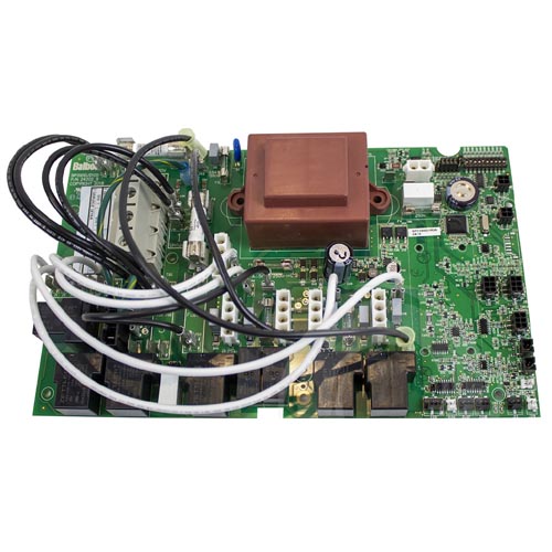
Q: I have a newer BP2100G1 board with a red transformer – is this compatible? A: Yes. Balboa updated the transformer design (from black to red) for improved load handling. Both versions are fully compatible with each other.
📥 Downloads & Resources
📄 BP2100G1 Tech Sheet – Complete wiring diagrams and setup configurations
📄 BP2100G1 Troubleshooting & Service Manual – Comprehensive diagnostics and repair guide
🏆 Why Choose the Balboa BP2100G1 PCB
✅ Genuine OEM Quality – Manufactured by Balboa Water Group, the world leader in spa control systems
✅ Direct Replacement – Engineered as an exact fit for BP2100 control boxes with no modifications required
✅ M7 Technology – Industry-leading temperature sensing eliminates unreliable pressure and flow switches
✅ Versatile Configuration – 18 setup options accommodate virtually any pump and accessory combination
✅ Future-Ready – WiFi compatibility allows smartphone control and integration with smart home systems
✅ Proven Reliability – Backed by Balboa’s decades of experience in spa electronics
✅ CE Certified – Fully compliant with European safety and electromagnetic compatibility standards
✅ Comprehensive Documentation – Detailed tech sheets and service manuals available
🤝 Why Buy from Parts4Tubs
✅ UK-Based Company – Local support from spa industry experts
✅ Fast UK Delivery – Get your spa back up and running quickly
✅ Expert Technical Advice – Our team understands Balboa systems inside and out
✅ Competitive Pricing – Quality parts at fair prices
✅ Full Warranty Support – Peace of mind with your purchase
✅ Easy Returns – 30-day returns policy on unused items
✅ Genuine Parts – Authorised Balboa components, not inferior copies
✅ Complete Solutions – Compatible pumps, heaters, sensors, and accessories all available
✨ Summary
The Balboa BP2100G1 PCB is the genuine OEM replacement board for BP2100 spa control systems, delivering reliable management of up to three pumps, a 3kW heater, lighting, ozone, and entertainment outputs. Featuring Balboa’s proven M7 dual-sensor technology and 18 configurable setups, this CE-certified board restores full functionality to your hot tub whilst offering WiFi-ready connectivity for modern smartphone control. Backed by Parts4Tubs’ expert UK support, this is the professional choice for spa repair and restoration.
Order today and get your hot tub back to perfect working order.
Finding and identifying a replacement Hot Tub Circuit Board (PCB)
If you are looking to replace a failed PCB on your Hot Tub’s spa pack, then quite often identifying the part that you need can be the hardest thing.
Firstly, you are looking for a model number on the actual circuit board itself. Having the model or serial of your hot tub is not going to help at this point, you need to find the number on the PCB itself.
Now, with certain brands of PCB, the number of the replacement PCB that you need is not going to match identically the one you are replacing. Why is that I hear you ask?
Well, normally, it is an updated version. This means that it might have updated firmware on the PCB or be a later revision. Normally, this means that the part number would be slightly different. This is usually indicated with a “12345678 -x” at the end of that part number where x indicated a firmware revision.
In some cases, there will be some following letters on the part number of the circuit board, “12345678 -x MAS” this can indicate that the PCB was used for an OEM meaning it was produced for a certain hot tub manufacturer and the letters identify the manufacturer.
This means if you source an original PCB, it will not have the letters, but will in most cases work just fine.
It can be confusing I know!
What if you can’t find a model number?
If you can’t find a model number on the PCB itself, then you need to look for a model number on the spa pack. Normally, there is a sticker on the outside of the spa pack that tells you the current ratings and input voltages etc and this will have a model number.
In general, most spa packs in the USA are manufactured by Balboa, Hydro-Quip, ACC or Gecko. I know I am generalising here, but if you have a spa pack that has the brand of your hot tub on, it will be an OEM so the key is identifying who made the original box.
From there, you can normally find an original PCB that you will be able to switch out.
For example, the Balboa VS (value series) is a very popular spa pack that has been used by multiple hot tub manufacturers under their own brand names. Whatever they have called it, strip it back and it is still a Balboa VS.
Visual Inspection
One of the most important things you can do when you are looking for a replacement is to visually inspect the PCB that you have versus the picture online of the replacement you are considering. They need to look the same even if there are the differences in firmware revisions or OEM part numbers, you should be visually replacing a PCB that looks like the one you have.
Configuring a replacement Hot Tub Circuit Board (PCB)
When you get a new PCB, you are more than likely going to need to configure it. Most PCBs have a number of different modes and setups that the can operate in. For this, you will need to manual or spec sheet to guide you.
For things like DIP switches, most of the time you can copy the settings from your original circuit board.
You may need to move jumpers or even wires to configure voltages – the key here is that you read the schematic and don’t expect the PCB to just work out of the box – it usually doesn’t.
Troubleshooting a Hot Tub Circuit Board (PCB)
Here are some common things you will see when you replace a PCB on a hot tub.
You press the buttons on the topside control and they don’t control the right parts (pumps or blower etc) – this is a mode configuration thing and you will either need to change some DIP switches on the PCB or an internal or low level programming mode on the topside control. Check the manual for how to do this.
To check this, unplug all of your kit – heater, pumps, blower and then turn on the PCB. If it trips with nothing plugged in, usually the voltage is incorrectly set and what is happening is that live current is being sent to the ground – because you have 4 wires into the PCB rather than 3. Current on the ground loop causes the trip. Check the settings to make sure it is configures for 230V.
It might not trip until you physically turn on a pump or a blower.
| Part# | 56391-04 |
|---|
You may also like…
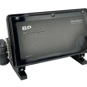
Control Boxes, Spa Packs & Topside Controls
Control Box Only
Related products
Control Boxes, Spa Packs & Topside Controls
Control Boxes, Spa Packs & Topside Controls

Control Boxes, Spa Packs & Topside Controls
Control Boxes, Spa Packs & Topside Controls
Control Boxes, Spa Packs & Topside Controls
Control Boxes, Spa Packs & Topside Controls