
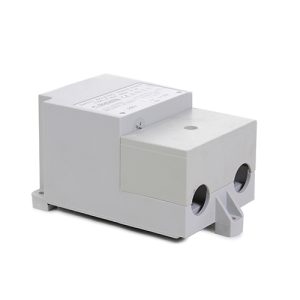
BIO-UV10 Ballast 35-48W High Output
£152.61 Inc VAT
Out of stock
Want to be notified when this product is back in stock?
BIO-UV10 Ballast 35-48W High Output
Precision Electronic Power Supply for Compact UV Systems
As a retailer of hot tub spare parts and pool equipment, I supply this specialized electronic ballast engineered specifically for BIO-UV’s UV10 series ultraviolet water treatment systems. The 35-48W high-output ballast represents advanced power conversion technology optimized for compact UV installations, delivering precisely regulated electrical power to germicidal lamps in the mid-power range. This ballast provides the sophisticated control and protection features required for reliable UV water treatment in residential pool, spa, and small commercial applications.
Understanding the UV10 Ballast Design
The BIO-UV10 Ballast functions as a dedicated electronic power supply tailored to the specific requirements of UV10 reactor systems. Operating within the 35-48W power range, this ballast handles UV lamps commonly deployed in compact water treatment applications where flow rates and treatment volumes suit residential pools, hot tubs, and small commercial installations. The ballast converts mains AC power into the high-frequency, high-voltage output necessary to strike and maintain stable UV lamp operation while incorporating intelligent control features that optimize performance and protect system components.
The “high output” designation indicates this ballast delivers enhanced power density compared to standard designs, maximizing UV-C emission at 254nm wavelength for effective germicidal action. Higher output within compact form factors requires sophisticated thermal management, efficient power conversion, and robust component selection to ensure reliability under continuous-duty operating conditions typical of pool and spa applications.
Power Range and Lamp Compatibility
The 35-48W power specification reflects the ballast’s ability to drive UV lamps within this wattage range, providing flexibility for different UV10 system configurations. This power level represents an optimal balance for compact UV reactors, delivering sufficient UV dosage for effective water treatment without requiring the larger chamber dimensions and higher flow restrictions associated with more powerful systems. The ballast automatically adapts its output characteristics to match connected lamp requirements, providing appropriate striking voltage to initiate lamp arc and maintaining correct operating current throughout the lamp’s service life.
This adaptive capability ensures optimal lamp performance regardless of minor variations between individual lamps or gradual changes in lamp characteristics as operating hours accumulate. The ballast’s control circuits continuously monitor lamp electrical characteristics, adjusting power delivery to maintain stable UV output despite these variations.
Electronic Ballast Architecture
Modern electronic ballasts like the BIO-UV10 unit employ high-frequency switching topologies that convert mains AC power (typically 230V or 120V depending on region) into precisely controlled high-frequency AC output. The ballast first rectifies incoming AC to DC, filters this DC to remove ripple, then uses high-frequency switching circuits (operating at 20-80 kHz) to generate the AC waveform required by UV lamps. This high-frequency operation eliminates visible flicker, improves lamp efficiency, and enables compact transformer designs compared to conventional mains-frequency magnetic ballasts.
The switching frequency and output waveform are optimized for mercury vapour discharge lamps used in UV water treatment, maintaining the proper mercury vapour pressure within the lamp for peak UV-C emission. The ballast’s output regulation compensates for mains voltage variations and lamp aging effects, delivering consistent UV dosage throughout the lamp’s rated life.
Compact Form Factor Engineering
The ballast’s physical dimensions (0.06m x 0.14m x 0.04m) reflect sophisticated engineering that packages substantial power-handling capability into a compact enclosure suitable for space-constrained installations. This miniaturization requires careful attention to component layout, thermal management, and electromagnetic compatibility. High-frequency switching generates heat that must be dissipated through the ballast housing, requiring adequate ventilation and proper mounting orientation to prevent overheating.
The compact design facilitates integration within UV system control enclosures or mounting adjacent to UV reactors in tight equipment spaces. The 0.19kg weight indicates solid construction with adequate heat-sinking for continuous-duty operation while remaining light enough for simple mounting without specialized support structures.
Protection and Safety Features
The BIO-UV10 Ballast incorporates comprehensive protection systems essential for reliable long-term operation. Over-current protection prevents damage if lamp faults or wiring issues create excessive current draw. Short-circuit protection immediately disconnects power upon detecting dangerous fault conditions. Open-circuit protection prevents ballast damage when lamp connections are interrupted or lamps fail to strike, conditions that could otherwise damage output stages.
Thermal monitoring tracks ballast temperature, reducing output or shutting down if excessive heat buildup threatens component reliability. End-of-lamp-life detection recognizes when UV lamps have degraded beyond effective service, indicated by increased striking voltage requirements or abnormal electrical characteristics. This intelligence enables proactive maintenance scheduling, replacing lamps before UV output falls below acceptable levels for water treatment.
Installation Requirements and Mounting
Proper ballast installation requires attention to ventilation, electrical connections, and environmental protection. The ballast must be mounted in locations providing adequate air circulation for convective cooling, typically with specified minimum clearances around the enclosure. Mounting orientation matters, as some designs optimize cooling for specific positions (horizontal versus vertical). The installation location should protect the ballast from direct water exposure, excessive humidity, and temperature extremes while remaining accessible for service.
Electrical connections require appropriately sized conductors for input power and lamp output circuits. Input wiring handles mains voltage and current, protected by circuit breakers or fuses rated according to ballast specifications. Output wiring to the UV lamp must accommodate high-frequency, high-voltage characteristics, using wire rated for the voltage levels involved and maintaining proper routing to minimize electromagnetic interference.
Efficiency and Operating Characteristics
Electronic ballasts typically achieve 85-92% efficiency in this power class, converting the majority of input power into useful lamp power with minimal losses to heat. This efficiency reduces operating costs compared to magnetic ballast alternatives and minimizes thermal burden on installation spaces. The high power factor (typically >0.95) achieved by electronic designs means electrical systems deliver power efficiently, drawing lower current from mains supplies for equivalent lamp power.
The ballast’s instant-start or rapid-start characteristics determine lamp ignition behavior. Some designs strike lamps within milliseconds of power application, while others incorporate preheat sequences that extend lamp life by warming electrodes before applying full striking voltage. The specific startup behavior affects system commissioning and restart procedures following power interruptions.
Service Life and Reliability
Quality electronic ballasts designed for continuous UV applications typically provide 40,000-60,000 hours of reliable service under proper operating conditions. This lifespan often exceeds multiple UV lamp replacement cycles, making the ballast a long-term infrastructure component. Proper thermal management through adequate ventilation is the single most important factor influencing ballast longevity, as elevated temperatures accelerate degradation of capacitors and other temperature-sensitive components.
The ballast’s environmental protection level, indicated by any IP rating, determines its resistance to humidity, dust, and chemical exposure. Pool equipment environments present challenging conditions, making adequate environmental protection essential for achieving rated service life.
Technical Specifications
| Specification | Details |
|---|---|
| Product Name | BIO-UV10 Ballast 35-48W High Output |
| SKU | 7111676150 |
| Category | UV System Spare Parts |
| Compatible Equipment | BIO-UV UV10 Series Systems |
| Power Range | 35-48W High Output |
| Weight | 0.19 kg |
| Dimensions (L x W x H) | 0.06m x 0.14m x 0.04m |
| Volume | 0.000336 m³ |
| Ballast Type | Electronic, High-Frequency |
| Primary Function | UV Lamp Power Supply and Regulation |
| Application | Compact UV Water Treatment Systems |
Optimizing Compact UV System Performance
The BIO-UV10 Ballast exemplifies how advanced electronics enable effective UV water treatment in compact installations suitable for residential and small commercial applications. By delivering precisely regulated, efficient power within a space-saving package, this ballast ensures UV10 systems achieve optimal germicidal performance while maintaining the reliability essential for continuous water treatment duty. The electronic design’s efficiency, regulation capability, and integrated protection features make it substantially superior to legacy magnetic ballast technology, justifying its role as a premium component in professional UV installations. Proper installation with adequate ventilation, correct electrical connections, and timely replacement when degradation occurs protects the investment UV systems represent while maintaining the consistent water quality that validates their installation in pool and spa applications.
| Weight | 0.19 Kilograms |
|---|---|
| Length | 0.06 Meters |
| Width | 0.14 Meters |
| Height | 0.04 Meters |
| Volume | 0.000336 CubicMeters |
| Supplier | GoldenC |
Related products
Spares
Spares