BIO-UV10 / 20 / 30 / 40 Cap
£85.31 Inc VAT
Out of stock
Want to be notified when this product is back in stock?
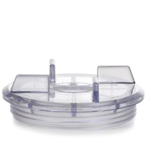
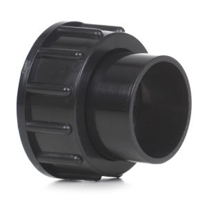
BIO-UV10 / 20 / 30 / 40 Cap
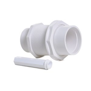
Essential Reactor End Cover for Multiple BIO-UV Models
As a retailer of hot tub spare parts and pool equipment, I supply this versatile end cap component designed for compatibility across multiple BIO-UV ultraviolet water treatment systems. This cap fits the UV10, UV20, UV30, and UV40 reactor models, serving as the critical closure element that seals the reactor chamber while providing access points for lamp installation, electrical connections, and system servicing. The cap’s multi-model compatibility makes it a valuable inventory item for service operations maintaining various BIO-UV system configurations.
Understanding End Cap Function
The reactor cap performs multiple essential functions within UV water treatment systems. Primarily, it provides a sealed closure for one end of the stainless steel reactor chamber, maintaining the watertight integrity necessary for pressurized operation. The cap incorporates mounting provisions for electrical components including lamp connectors, ballast connections, and potentially status indicators or control elements depending on the specific system configuration.
The cap design accommodates the UV lamp assembly, providing a sealed entry point where the lamp connector penetrates the pressure boundary. This interface must maintain watertight sealing while allowing electrical connections to pass through, requiring precision engineering of gasket surfaces and penetration assemblies. The cap typically houses or supports components such as lamp holders, electrical terminals, protective covers for electrical elements, and mounting provisions for external control boxes or ballasts.
Multi-Model Compatibility Design
The cap’s compatibility across UV10, UV20, UV30, and UV40 models reflects BIO-UV’s modular design philosophy, where common components are shared across product ranges to simplify manufacturing, reduce inventory complexity, and streamline service procedures. These models represent different power ratings and flow capacities within BIO-UV’s product lineup, likely utilizing similar reactor chamber diameters and end cap mounting arrangements despite differences in lamp power, chamber length, or flow optimization features.
This standardization benefits both manufacturers and end users. Service technicians can stock a single cap design to service multiple system types, reducing inventory requirements and ensuring parts availability. The commonality also suggests these systems share electrical connection standards and lamp mounting approaches, further simplifying service procedures and component sourcing.
Structural and Sealing Requirements
The cap must withstand system operating pressure, typically several bar in pool and spa applications, while maintaining seal integrity throughout thermal cycles, pressure variations, and long-term exposure to water and chemicals. The cap material, typically stainless steel or engineered plastic, must resist corrosion from treated water and provide adequate structural strength to support internal components and withstand mounting loads.
Sealing interfaces utilize O-rings or gaskets compressed between the cap and reactor chamber body. These sealing surfaces require precision machining to ensure uniform compression around the seal circumference, preventing leak paths that would compromise system operation. The cap mounting mechanism, whether threaded, clamped, or bolted, must maintain adequate sealing force throughout the operating temperature range and resist loosening from vibration.
Electrical Penetrations and Protection
Electrical components integrated with or mounted to the cap require protection from moisture ingress that could cause short circuits, corrosion, or electrical hazards. The cap design incorporates sealed penetrations for lamp connections, utilizing grommets, compression fittings, or sealed connectors that maintain watertight integrity while allowing electrical current passage. Some cap designs include protective hoods or covers that shield electrical terminals and connections from ambient moisture and accidental contact.
The electrical integration must accommodate the high voltages generated by UV lamp ballasts, requiring adequate insulation and clearance distances between conductive elements. Ground connections typically route through the cap assembly, providing safety paths for fault currents while the overall design must prevent water from reaching electrical components even if primary seals degrade.
Installation and Service Procedures
Proper cap installation requires attention to seal condition, surface cleanliness, and mounting torque specifications. Before installing a replacement cap, technicians should inspect sealing surfaces on both the cap and reactor body for damage, corrosion, or deposits that could compromise sealing. O-rings or gaskets should be replaced with each cap removal, as compression set and handling damage can prevent reliable resealing.
During installation, proper alignment ensures uniform seal compression and prevents cross-threading of fasteners or misalignment of electrical penetrations. Tightening sequences for multi-bolt caps typically follow patterns that achieve even loading around the seal circumference, similar to cylinder head bolt tightening in engines. After installation, leak testing confirms seal integrity before returning the system to service.
Degradation Mechanisms and Inspection
Reactor caps experience wear from several mechanisms during service. Threaded connections can become damaged from cross-threading, over-tightening, or corrosion, making removal difficult and preventing proper sealing during reinstallation. Sealing surfaces may develop scratches, corrosion pitting, or deposits that create leak paths. Electrical penetrations can degrade from heat, chemical exposure, or physical damage, allowing moisture ingress to electrical components.
Regular inspection during lamp replacement or system maintenance allows early detection of cap degradation. Signs requiring attention include visible corrosion or damage to structural elements, leakage from seal areas, deterioration of electrical penetrations or protective covers, damaged threads, or deformation from over-tightening. Timely replacement prevents minor issues from escalating to system failures or safety hazards.
Compatibility Verification
While this cap design serves multiple models (UV10, UV20, UV30, UV40), proper application requires verification that the specific system model falls within the compatible range. Model numbers typically reflect power ratings or flow capacities, with these designations indicating systems sharing common reactor chamber dimensions and cap mounting specifications. Technical documentation or consultation with BIO-UV resources confirms compatibility for specific installations.
The cap’s design may incorporate model-specific features or variations despite overall compatibility, such as different electrical penetration configurations or mounting provisions for model-specific components. Understanding these variations ensures proper component selection and installation for each application.
Technical Specifications
| Specification | Details |
|---|---|
| Product Name | BIO-UV10/20/30/40 Cap |
| SKU | 7111676180 |
| Category | UV System Spare Parts |
| Compatible Models | BIO-UV UV10, UV20, UV30, UV40 |
| Component Type | Reactor End Cap Assembly |
| Primary Functions | Chamber Sealing, Lamp Access, Electrical Integration |
| Application | UV Reactor Chamber Closure |
| Material Type | Corrosion-Resistant (Stainless Steel or Engineered Plastic) |
Maintaining System Integrity
The reactor cap represents a critical pressure boundary component whose proper function is essential for safe, leak-free UV system operation. By providing sealed closure while accommodating necessary electrical penetrations and lamp access, this component enables the UV reactor to perform its water treatment function reliably. Multi-model compatibility adds practical value for service operations, streamlining inventory and simplifying maintenance procedures across different system capacities. Proper installation with fresh sealing elements and timely replacement when degradation appears ensures the reactor maintains pressure integrity and electrical safety throughout its service life, protecting the substantial investment UV water treatment systems represent while delivering the consistent performance that validates their installation in pool and spa applications.
| Supplier | GoldenC |
|---|
Related products
Spares

Spares
Spares