BIO-UV Switch
£13.78 Inc VAT
Out of stock
Want to be notified when this product is back in stock?
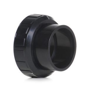
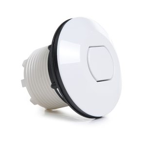
BIO-UV Switch
Essential Control Component for UV System Operation
As a retailer of hot tub spare parts and pool equipment, I supply this fundamental control switch for BIO-UV ultraviolet water treatment systems. The switch serves as the primary operator interface for controlling UV system power, enabling users to manually activate or deactivate the UV lamp and associated electronics. While appearing to be a simple on/off device, this switch must reliably handle the electrical loads associated with UV ballast circuits while providing safe, ergonomic control access and withstanding the environmental conditions encountered in pool equipment installations.
Understanding Switch Function in UV Systems
The switch in a BIO-UV system provides manual control over power delivery to the electronic ballast and UV lamp assembly. When actuated to the “on” position, the switch completes the electrical circuit allowing mains power to flow to the ballast, which then generates the high voltages required to strike and maintain the UV lamp. In the “off” position, the switch interrupts power flow, de-energizing the ballast and extinguishing the UV lamp.
This control function serves multiple purposes within pool and spa installations. Operators can deactivate UV systems during maintenance procedures without requiring access to circuit breakers or disconnection of hard-wired power connections. The switch enables seasonal shutdown of UV equipment in outdoor installations where winterization requires complete system deactivation. For troubleshooting purposes, the readily accessible switch allows technicians to cycle power to the UV system without navigating to remote electrical panels.
Electrical Specifications and Load Requirements
The BIO-UV switch must be appropriately rated to handle the electrical characteristics of UV lamp ballast circuits. Electronic ballasts draw significant inrush current during startup as internal capacitors charge and the lamp striking sequence initiates. The switch contacts must withstand these current transients without welding closed or degrading through arcing damage. The switch’s voltage rating must provide adequate safety margins above the mains supply voltage encountered in typical pool equipment installations.
Contact materials within the switch are selected for their ability to interrupt inductive loads without excessive arcing. UV ballast circuits present inductive characteristics due to transformer windings and choke components, making the breaking of current more challenging than simple resistive loads. The switch design incorporates features such as arc suppression chambers or contact materials that resist erosion from repeated switching under load.
Mechanical Design and Actuation
The switch mechanism provides positive tactile feedback to operators, with distinct positions for “on” and “off” states. The actuation force is balanced to prevent accidental switching while remaining easily operable during routine use. Switch mechanisms typically employ snap-action contacts that transition quickly between states, minimizing the dwell time when contacts are partially separated and arcing potential is highest.
The switch housing protects internal components from environmental contamination while providing mounting provisions compatible with BIO-UV system enclosures. Housing materials resist degradation from UV radiation exposure, humidity, and temperature variations encountered near pool equipment. The actuator design accommodates operation by personnel wearing work gloves, with clear position indication for the current switch state.
Environmental Considerations and Protection
Pool equipment environments present challenging conditions for electrical components. The switch must function reliably despite exposure to elevated humidity levels, temperature variations from equipment operation, and potential contamination from airborne pool chemicals. Many UV system switches incorporate sealed constructions or protective ratings (IP ratings) that prevent moisture ingress into the contact chamber.
Corrosion resistance is essential for long-term reliability, particularly for terminal connections and mounting hardware. The switch assembly typically includes provisions for proper grounding connections, ensuring electrical safety even if housing moisture accumulation occurs. Cable entry points incorporate strain relief features that prevent mechanical stress from being transmitted to electrical connections within the switch.
Installation and Wiring Requirements
Proper switch installation requires attention to electrical safety codes and manufacturer specifications. Wiring to switch terminals must use conductors of appropriate gauge for the current load, with secure terminations that resist loosening from vibration or thermal cycling. Terminal connections should be verified for tightness and conductor retention before energizing the circuit.
The switch positioning within the UV system enclosure must provide operator access while maintaining appropriate clearances from other electrical components. Many installations position switches on the front panel of control enclosures where they’re readily accessible without requiring removal of protective covers. Proper labeling identifies the switch function, particularly in installations with multiple UV systems or complex equipment arrays.
Safety Interlocks and System Integration
In some UV system configurations, the manual switch works in conjunction with automatic control elements such as flow switches that prevent lamp operation without water flow, timers that coordinate UV operation with filtration schedules, or interlock circuits that disable UV power when access panels are opened. The manual switch typically provides override capability, allowing operators to control UV power independently of automated control functions when necessary for maintenance or troubleshooting.
The switch may integrate with status indication systems, triggering indicator lights that confirm UV system operation or facilitating remote monitoring of equipment status. These integration features enhance operational visibility while maintaining straightforward manual control capability.
Degradation and Replacement Indicators
Switch mechanisms experience wear through repeated actuation cycles and electrical stress from load interruption. Common degradation indicators include loose or uncertain feel during actuation, failure to reliably make or break electrical contact, visible arcing at contacts during switching, overheating of the switch body, or burning odours from contact arcing damage.
Contact erosion from repeated switching gradually reduces the contact area available for current transfer, increasing electrical resistance and heat generation in a progressive failure mode. Regular inspection during maintenance intervals allows identification of degraded switches before they cause equipment failures or safety hazards. Replacement of switches showing signs of degradation prevents unexpected system failures and maintains electrical safety.
Technical Specifications
| Specification | Details |
|---|---|
| Product Name | BIO-UV Switch |
| SKU | 7111676193 |
| Category | UV System Spare Parts |
| Compatible Equipment | BIO-UV UV Systems |
| Weight | 0.02 kg |
| Dimensions (L x W x H) | 0.04m x 0.04m x 0.03m |
| Volume | 4.8 × 10⁻⁵ m³ |
| Component Type | Power Control Switch |
| Primary Function | UV System On/Off Control |
| Application | Manual Power Control |
Maintaining Safe and Reliable Operation
The control switch represents the operator’s primary interface with UV system power control, making its reliable function essential for both operational convenience and electrical safety. By maintaining properly functioning switches and replacing degraded components during scheduled maintenance, UV system operators ensure safe, predictable control over water treatment equipment. The switch’s role in enabling manual power control, facilitating maintenance procedures, and providing emergency shutdown capability makes it a critical component despite its apparent simplicity, warranting attention during routine equipment inspection and service procedures.
| Weight | 0.02 Kilograms |
|---|---|
| Length | 0.04 Meters |
| Width | 0.04 Meters |
| Height | 0.03 Meters |
| Volume | 4.8E-5 CubicMeters |
| Supplier | GoldenC |
Related products
Spares
Spares
Spares
Spares