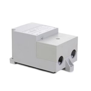

BIO-UV Indicator 5V with LED
£54.73 Inc VAT
Out of stock
Want to be notified when this product is back in stock?
BIO-UV Indicator 5V with LED
Visual System Status Monitor for UV Reactor Control
As a retailer of hot tub spare parts and pool equipment, I supply this essential replacement indicator light component for BIO-UV ultraviolet water treatment systems. The 5V LED indicator serves as the operator’s primary visual interface with the UV system, providing real-time status information about lamp operation and system health. This small but critical component enables operators to monitor UV system performance at a glance, identify potential issues before they compromise water treatment effectiveness, and confirm proper system operation without requiring specialized test equipment or technical expertise.
Understanding UV System Status Monitoring
Modern UV water treatment systems incorporate sophisticated monitoring capabilities to ensure consistent disinfection performance and alert operators to conditions requiring attention. The LED indicator translates electronic signals from the UV system’s control circuitry into visible light displays that communicate system status through colour, intensity, or flashing patterns. This visual feedback system enables rapid assessment of UV equipment operation during routine inspections and immediate identification of fault conditions.
The indicator typically mounts on the UV reactor housing or control panel where it remains visible to maintenance personnel during normal operations. Its position allows quick status checks without requiring access to internal components or interruption of water treatment processes. The LED’s visual output provides continuous confirmation that the UV system is energized and functioning correctly, or alerts operators to conditions such as lamp failure, low UV output, or electrical faults requiring intervention.
LED Technology and Low Voltage Operation
The 5V operating voltage specification indicates this indicator uses low-voltage LED technology, which offers several advantages over traditional incandescent indicator lamps. LEDs consume minimal electrical power, generate negligible heat, and provide exceptionally long service life compared to filament-based indicators. The low voltage operation enhances electrical safety while simplifying integration with modern electronic control systems that operate on similar voltage levels.
LED indicators deliver superior visibility through bright, focused light output that remains clearly visible in various ambient lighting conditions, from dimly lit equipment rooms to brightly lit pool facility environments. The solid-state construction of LED technology provides excellent resistance to vibration and mechanical shock, important characteristics for equipment operating in proximity to pump motors and filtration systems.
Indicator Function in System Operation
The LED indicator serves multiple roles within the UV system’s operational framework. During normal operation, the indicator confirms that the UV lamp is energized and the control system is functioning properly. This continuous visual feedback assures operators that water flowing through the reactor is receiving appropriate UV treatment for pathogen inactivation. Regular observation of the indicator during facility inspections provides early warning of developing issues before they escalate to system failures.
When fault conditions occur, the indicator’s behavior changes to alert operators that attention is required. Depending on system design, the indicator may change color, begin flashing, or extinguish completely to signal different fault types. This immediate visual notification enables rapid response to issues such as lamp failure, electrical problems, or control system malfunctions, minimizing periods when water treatment may be compromised.
Lamp Life Monitoring and Maintenance Scheduling
Many UV systems use the LED indicator in conjunction with lamp hour monitoring circuits to alert operators when UV lamp replacement becomes necessary. UV lamps gradually lose germicidal effectiveness over their operational life even though they continue producing visible light. The indicator may change behavior patterns as accumulated lamp hours approach replacement intervals, providing advance warning that maintenance should be scheduled.
This proactive notification system helps ensure UV lamps are replaced based on actual operating hours rather than arbitrary calendar intervals, optimizing both treatment effectiveness and lamp utilization. The visual alert eliminates reliance on manual record-keeping or complex calculations to determine lamp replacement timing, reducing the risk of operating with degraded UV output.
Electrical Integration and Control System Interface
The 5V LED indicator integrates with the UV system’s electronic control circuitry, receiving power and control signals that determine its operational state. The indicator’s electrical characteristics must match the control system’s output specifications to ensure proper function and reliable communication of system status. The component’s design incorporates current-limiting elements to protect the LED from overvoltage conditions while ensuring adequate brightness for visibility.
Proper electrical connection during installation requires attention to polarity, as LED devices function in only one direction. Incorrect polarity connection prevents illumination but typically does not damage the component. Following manufacturer wiring diagrams ensures correct installation and reliable indicator operation.
Replacement and Maintenance Considerations
LED indicators generally provide years of reliable service but may eventually require replacement due to LED degradation, moisture intrusion, mechanical damage, or electronic component failure. Dimming of the indicator over time, flickering, failure to illuminate, or continuously lit regardless of system status all indicate replacement may be necessary. Having spare indicators available minimizes system downtime when replacement becomes required.
Replacement procedures typically involve disconnecting electrical connections, removing the failed indicator from its mounting location, and installing the new component with proper polarity observation. Some systems may require control system reset or recalibration following indicator replacement to ensure proper communication between monitoring circuits and the display element.
Technical Specifications
| Specification | Details |
|---|---|
| Product Name | BIO-UV Indicator 5V with LED |
| SKU | 7111676190 |
| Category | UV System Spare Parts |
| Compatible Equipment | BIO-UV UV Reactor Systems |
| Operating Voltage | 5V DC |
| Weight | 0.01 kg |
| Dimensions (L x W x H) | 0.14m x 0.09m x 0.03m |
| Volume | 0.000378 m³ |
| Technology | LED (Light Emitting Diode) |
| Primary Function | System Status Visual Indication |
| Application | Lamp Operation Monitoring |
Maintaining Operational Visibility
The LED indicator represents the operator’s window into UV system health and performance. This simple visual interface eliminates ambiguity about system operation, providing immediate confirmation that water treatment is proceeding normally or alerting maintenance personnel that intervention is required. By maintaining functional indicators and responding promptly to status changes they communicate, UV system operators ensure consistent water quality while protecting the significant investment these treatment systems represent.
The relatively modest cost of replacement indicators makes proactive replacement sensible when indicators show signs of degradation, ensuring reliable system monitoring without risking periods of undetected malfunction that could compromise water treatment effectiveness.
| Weight | 0.01 Kilograms |
|---|---|
| Length | 0.14 Meters |
| Width | 0.09 Meters |
| Height | 0.03 Meters |
| Volume | 0.000378 CubicMeters |
| Supplier | GoldenC |
Related products
Spares