Balboa Expander Board Relay 30amp (GS-GL) – High-Current Pump Expansion Module
£48.48 Inc VAT
12 in stock
⚡ Balboa Expander Board Relay 30amp (GS-GL) – High-Current Pump Expansion Module
Heavy-duty relay expansion board with 30A fuse protection to add one single-speed pump to your Balboa GS and GL control systems.
📋 Product Overview
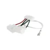
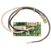
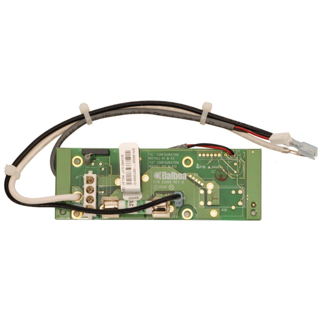
This PCB is used in many Balboa GS and GL Systems to add a 1-speed pump protected by a 30A fuse. The Balboa Expander Board Relay 30amp is designed for high-current pump applications, extending the capabilities of GS and GL series control boxes with robust overcurrent protection.
This expansion module connects to your existing GS or GL main board and provides the additional relay circuitry needed to operate an extra single-speed pump, featuring a 30A fuse for safe operation of higher-current pumps.
✨ Key Features
✅ 230V / 50Hz Operation – Designed for UK and European electrical systems
✅ 30A Fuse Protection – Heavy-duty overcurrent protection for high-current pumps
✅ Single-Speed Pump Support – Controls one additional 1-speed pump
✅ GS and GL Compatible – Works with many Balboa GS and GL control boxes
✅ Official Balboa Part – Part number 55025
✅ Robust Design – Larger board for high-current applications
🔧 Technical Specifications
| Specification | Value |
|---|---|
| Brand | Balboa |
| Balboa Part Number | 55025 |
| Model / Series | GS and GL |
| Product Type | Expander Board |
| Input Voltage | 230V |
| Frequency | 50Hz |
| Output Support | One additional single-speed pump |
| Fuse Protection | 30A |
| Length | 135 mm |
| Height | 64 mm |
✅ Compatibility Guide
Compatible Control Systems
| Control System | Compatibility |
|---|---|
| Balboa GS series control boxes | ✅ Compatible (some models) |
| Balboa GL series control boxes | ✅ Compatible (some models) |
Note: This board is compatible with some Balboa GS and GL control boxes. Please verify your specific system before ordering.
GS-GL Expander Board Comparison
| Requirement | Recommended Board | Fuse |
|---|---|---|
| Standard current pump/blower | CB-EX535 (part 53547) | Not specified |
| High-current pump (30A) | This board – CB-EX550 (part 55025) | 30A |
Choose this board if you need 30A fuse protection for a higher-current pump.
⚙️ Board Functions
Pump Expansion
| Function | Specification |
|---|---|
| Output Type | Single-speed pump |
| Number of Outputs | 1 |
| Fuse Protection | 30A |
How It Works
The expander board connects to your GS or GL main control board and provides:
- Additional relay control for a single-speed pump
- 30A fuse protection for high-current pump circuit
- Integration with existing topside panel controls
- Safe switching for larger pump motors
Why 30A Protection?
The 30A fuse rating allows this board to safely handle higher-current pumps that would exceed the capacity of standard expander boards. This is essential for larger jet pumps or pumps with higher starting currents.
🛠️ Installation Requirements
⚠️ IMPORTANT: This should be done by an experienced tradesman or a competent individual as a faulty install could result in board damage and invalidate warranty.
Pre-Installation Checklist
- [ ] Verify you have a compatible GS or GL control system
- [ ] Confirm your pump requires 30A protection
- [ ] Check pump current draw does not exceed 30A
- [ ] Disconnect all power at the isolator/breaker
- [ ] Photograph existing wiring connections
- [ ] Allow capacitors to discharge (wait 5 minutes minimum)
Electrical Requirements
| Requirement | Specification |
|---|---|
| Supply Voltage | 230V |
| Frequency | 50Hz |
| Fuse Rating | 30A (provided on board) |
| RCD Protection | Required (30mA recommended) |
| Earth Connection | Mandatory |
💡 Tip: This board must be installed in conjunction with a compatible GS or GL main board – it cannot operate independently.
⚠️ Safety Warnings
Electrical Safety
- ⚠️ ALWAYS disconnect power before any work
- ⚠️ Installation by experienced tradesman or competent individual required
- ⚠️ Ensure correct voltage supply (230V, 50Hz)
- ⚠️ Verify RCD protection is installed and functioning
- ⚠️ Never operate spa with covers removed from electrical components
Important Notes
- ⚠️ This is an expander board – not a main control PCB
- ⚠️ This PCB is for some Balboa GS and GL control boxes only
- ⚠️ Must not be fitted to any other device/product
- ⚠️ Faulty install could result in board damage
- ⚠️ Faulty install will invalidate warranty
- ⚠️ Ensure pump current does not exceed 30A rating
🎯 Ideal Applications
| Application | Suitability | Notes |
|---|---|---|
| ♨️ Balboa GS Series Systems | ✅ Compatible | Check specific model |
| ♨️ Balboa GL Series Systems | ✅ Compatible | Check specific model |
| ♨️ High-Current Pump Addition | ✅ Ideal | 30A fuse protection |
| ♨️ Large Jet Pumps | ✅ Ideal | For pumps requiring >15A |
| ♨️ Expander Replacement | ✅ Direct replacement | Part number 55025 |
This board is designed for:
- Adding a high-current single-speed pump to GS or GL systems
- Replacing faulty 30A expander boards (part 55025)
- Pumps that exceed the capacity of standard CB-EX535 expander
- Applications requiring robust overcurrent protection
❓ Frequently Asked Questions
Q: Is this a main control board or an expander? A: This is an expander board that works alongside your GS or GL main control board. It adds the capability to control one additional single-speed pump with 30A protection.
Q: What’s the difference between this and the CB-EX535? A: This board (CB-EX550) has 30A fuse protection and is larger (135×64mm vs 80×41mm). The CB-EX535 does not have specified fuse protection and is smaller. Use this board for higher-current pumps.
Q: Can I use this for a blower? A: This board is specified for a single-speed pump only. For blower applications, consider the CB-EX535 which supports pump OR blower.
Q: Can I add a 2-speed pump with this board? A: No, this board supports single-speed pumps only. For 2-speed pump expansion, you would need a different expander.
Q: Will this work with all GS and GL systems? A: It works with some Balboa GS and GL control boxes. Please verify your specific system compatibility before ordering.
Q: What is the Balboa part number? A: The official Balboa part number is 55025.
Q: Is this board larger than other expanders? A: Yes, at 135mm × 64mm, this is the largest GS-GL expander board due to the 30A relay and fuse requirements.
🏆 Why Choose the Balboa GS-GL 30A Relay Expander Board
- ✅ Official Balboa Part – Part number 55025
- ✅ 230V / 50Hz – Designed for UK electrical systems
- ✅ 30A Fuse Protection – Heavy-duty overcurrent safety
- ✅ High-Current Capable – For larger pump motors
- ✅ Wide Compatibility – Works with many GS and GL systems
- ✅ Proven Reliability – Balboa engineering quality
- ✅ Robust Construction – Larger board for high-current applications
🤝 Why Buy From Parts4Tubs
- ✅ UK-based company with local support
- ✅ Fast UK delivery
- ✅ Expert technical advice from spa specialists
- ✅ Competitive pricing
- ✅ Full warranty support
- ✅ Easy returns within 30 days (unfitted items)
- ✅ Compatible parts and accessories available
- ✅ Help with identifying correct replacement board
✨ Summary
The Balboa Expander Board Relay 30amp (GS-GL) is a heavy-duty expansion module designed for many Balboa GS and GL control systems. Operating at 230V / 50Hz, this board (Balboa part number 55025) adds the capability to control one additional single-speed pump with robust 30A fuse protection. With dimensions of 135mm × 64mm, it’s the largest GS-GL expander available, designed to handle high-current pump applications. Choose this board over the standard CB-EX535 when you need 30A fuse protection for larger pumps. This is an expander board, not a main control PCB – it requires a GS or GL main board to function. Installation by an experienced tradesman or competent individual is required.
Finding and identifying a replacement Hot Tub Circuit Board (PCB)
If you are looking to replace a failed PCB on your Hot Tub’s spa pack, then quite often identifying the part that you need can be the hardest thing.
Firstly, you are looking for a model number on the actual circuit board itself. Having the model or serial of your hot tub is not going to help at this point, you need to find the number on the PCB itself.
Now, with certain brands of PCB, the number of the replacement PCB that you need is not going to match identically the one you are replacing. Why is that I hear you ask?
Well, normally, it is an updated version. This means that it might have updated firmware on the PCB or be a later revision. Normally, this means that the part number would be slightly different. This is usually indicated with a “12345678 -x” at the end of that part number where x indicated a firmware revision.
In some cases, there will be some following letters on the part number of the circuit board, “12345678 -x MAS” this can indicate that the PCB was used for an OEM meaning it was produced for a certain hot tub manufacturer and the letters identify the manufacturer.
This means if you source an original PCB, it will not have the letters, but will in most cases work just fine.
It can be confusing I know!
What if you can’t find a model number?
If you can’t find a model number on the PCB itself, then you need to look for a model number on the spa pack. Normally, there is a sticker on the outside of the spa pack that tells you the current ratings and input voltages etc and this will have a model number.
In general, most spa packs in the USA are manufactured by Balboa, Hydro-Quip, ACC or Gecko. I know I am generalising here, but if you have a spa pack that has the brand of your hot tub on, it will be an OEM so the key is identifying who made the original box.
From there, you can normally find an original PCB that you will be able to switch out.
For example, the Balboa VS (value series) is a very popular spa pack that has been used by multiple hot tub manufacturers under their own brand names. Whatever they have called it, strip it back and it is still a Balboa VS.
Visual Inspection
One of the most important things you can do when you are looking for a replacement is to visually inspect the PCB that you have versus the picture online of the replacement you are considering. They need to look the same even if there are the differences in firmware revisions or OEM part numbers, you should be visually replacing a PCB that looks like the one you have.
Configuring a replacement Hot Tub Circuit Board (PCB)
When you get a new PCB, you are more than likely going to need to configure it. Most PCBs have a number of different modes and setups that the can operate in. For this, you will need to manual or spec sheet to guide you.
For things like DIP switches, most of the time you can copy the settings from your original circuit board.
You may need to move jumpers or even wires to configure voltages – the key here is that you read the schematic and don’t expect the PCB to just work out of the box – it usually doesn’t.
Troubleshooting a Hot Tub Circuit Board (PCB)
Here are some common things you will see when you replace a PCB on a hot tub.
You press the buttons on the topside control and they don’t control the right parts (pumps or blower etc) – this is a mode configuration thing and you will either need to change some DIP switches on the PCB or an internal or low level programming mode on the topside control. Check the manual for how to do this.
To check this, unplug all of your kit – heater, pumps, blower and then turn on the PCB. If it trips with nothing plugged in, usually the voltage is incorrectly set and what is happening is that live current is being sent to the ground – because you have 4 wires into the PCB rather than 3. Current on the ground loop causes the trip. Check the settings to make sure it is configures for 230V.
It might not trip until you physically turn on a pump or a blower.
| Part# | 55025 |
|---|
Related products
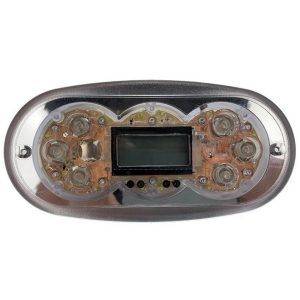
Control Boxes, Spa Packs & Topside Controls

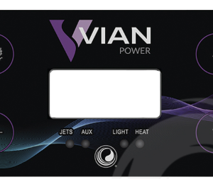
Control Boxes, Spa Packs & Topside Controls
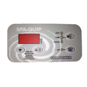
Control Boxes, Spa Packs & Topside Controls
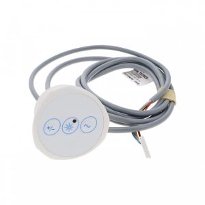
Control Boxes, Spa Packs & Topside Controls
Control Boxes, Spa Packs & Topside Controls
Control Boxes, Spa Packs & Topside Controls
Control Boxes, Spa Packs & Topside Controls
Control Boxes, Spa Packs & Topside Controls