Balboa Exp. Board 2 Pump Relay (GS523DZ)
£52.43 Inc VAT
8 in stock
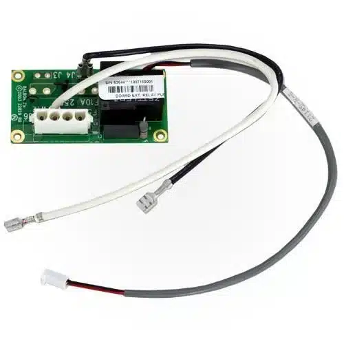
⚡ Balboa X-P332 CE Expander Board (55138) – 2-Pump Relay for GS & BP Systems
Expand your spa’s pump capacity with this genuine Balboa 2-relay expander board for GS523DZ and compatible systems.
📋 Product Overview
The Balboa X-P332 CE Expander Board (Part Number 55138) is a genuine Balboa Water Group relay expansion card that adds additional pump control capability to compatible GS and BP series spa control systems. This 2-relay, 3-wire expander board enables you to control up to two additional pumps or a combination of pump and blower, protected by a robust 30A fuse.
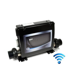
Originally designed for the GS523DZ control system, this expander board is pre-installed in several Balboa systems including the GS520DZ, GS523DZ, BP6013G2, BP6013G3, and BP2100. As a direct replacement part, it allows you to restore full functionality to systems with a failed expander board or replace older versions in compatible systems.
This is the CE-rated version specifically designed for European 230V 50Hz electrical systems, featuring the distinctive black transformer found on older GS and BP series boards.
⭐ Key Features
✅ Genuine Balboa Part (PN 55138) – Manufactured by Balboa Water Group for guaranteed compatibility
✅ 2-Relay Configuration – Controls two separate pump circuits from a single board
✅ 30A Fuse Protection – Built-in 30A 480V fuse protects pump circuits
✅ Flexible Output Options – Supports 2-speed pump, two 1-speed pumps, or pump plus blower
✅ 3-Wire Control – Standard 3-wire connection to main board EXT RLY terminal
✅ CE Rated – Designed for European 230V 50Hz electrical systems
✅ Compact Design – 115mm × 47mm footprint fits standard expander mounting positions
✅ Wide Compatibility – Works with GS523DZ, GS520DZ, BP2100, BP6013 and other compatible systems
🔧 Technical Specifications
| Specification | Value |
|---|---|
| Balboa Part Number | 55138 |
| Board Designation | X-P332 CE |
| Manufacturer | Balboa Water Group |
| Board Type | 2-Relay Expander PCB |
| Wire Configuration | 3-Wire |
| System Voltage | 230VAC |
| Frequency | 50Hz |
| On-Board Fuse | 30A 480V |
| Relay Count | 2 |
| Board Length | 115mm |
| Board Height | 47mm |
| Replaces | Older X-P332 versions |
| Replaced By | 59097 (newer revision) |
🔌 Output Configurations
The X-P332 CE expander board supports multiple output configurations depending on your spa requirements:
| Configuration | Components | Notes |
|---|---|---|
| Option 1 | 1 × 2-Speed Pump | Direct connection, no splitter required |
| Option 2 | 2 × 1-Speed Pumps | Requires PS-23 AMP splitter cable |
| Option 3 | 1 × 1-Speed Pump + 1 × Blower | Requires PS-23 AMP splitter cable |
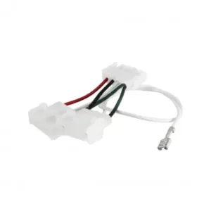
PS-23 Splitter Cable
When using two separate devices (Option 2 or 3), the PS-23 splitter cable (PN 22909) is required to split the output to both devices.
🔗 Compatibility Guide
Compatible Control Systems
| System | Compatibility | Notes |
|---|---|---|
| GS523DZ | ✅ Direct fit | Pre-installed from factory |
| GS520DZ | ✅ Direct fit | Pre-installed from factory |
| GS520SZ | ✅ Compatible | May require mounting kit |
| BP2100 | ✅ Compatible | Older systems with black transformer |
| BP6013G2 | ✅ Compatible | Pre-installed from factory |
| BP6013G3 | ✅ Compatible | Pre-installed from factory |
| Other GS Series | ⚠️ Check compatibility | Systems with black transformer |
| GL Series | ⚠️ Check compatibility | Older systems with EXT RLY connector |
⚠️ Important: This is a replacement part only. It cannot be fitted to control boards that did not originally have an expander board installed and programmed.
System Part Numbers (GS523DZ)
| Component | Part Number |
|---|---|
| Complete GS523DZ System | 54763-01 / 54763-02 |
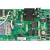
| Main PCBA | 55857-01 |
| PCB GS500Z | 22015 Rev B |
| Expander Board X-P332 CE | 55138 |
| PS-23 Splitter Cable | 22909 REV B |
⚙️ GS523DZ System Outputs (With Expander)
When installed in a GS523DZ system, the complete system provides:
| Output | Specification |
|---|---|
| Pump 1 | 230V, 2-Speed |
| Pump 2 | 230V, 1-Speed (via expander) |
| Pump 3 | 230V, 1-Speed (via expander with splitter) |
| Blower | 230V, 1-Speed |
| Ozone | 230V |
| Circulation Pump | 230V (Setup 2 only) |
| Spa Light | 10V |
| A/V (Stereo) | 230V |
| Heater | 3.0kW |
🛠️ Installation Requirements
⚠️ IMPORTANT: All electrical work must be carried out by a qualified electrician in accordance with BS 7671 (IET Wiring Regulations).
Pre-Installation Checklist
- [ ] Confirm your system originally had an expander board installed
- [ ] Verify the system has the EXT RLY connector on the main board
- [ ] Disconnect all power at the main breaker
- [ ] Allow capacitors to discharge (wait minimum 5 minutes)
- [ ] Photograph existing wiring before removal
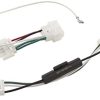
Wiring Connections (GS523DZ)
| Connection | From | To |
|---|---|---|
| Control Wire | J1 on X-P332 | J1 on main board (via splitter) |
| Pump 2 | J7 on X-P332 | Pump 2 motor |
| Pump 3 | J6 on X-P332 | Pump 3 motor (via splitter) |
| Power | W1 on X-P332 | J57 or J58 on main PCBA |
Persistent Memory Reset
After installing or replacing the expander board, you must reset persistent memory:
- Power down by disconnecting power source
- Put a jumper across J43 on main board (covering both pins)
- Power up – wait until display shows specific characters
- Power down again
- Remove jumper from J43 (leave on 1 pin only)
- Power up again
⚠️ Safety Warnings
Electrical Safety
⚠️ ALWAYS disconnect power at the main breaker before any work on the control system.
⚠️ Main power to system should be turned OFF BEFORE adjusting DIP switches.
⚠️ Persistent Memory (J43) must be RESET to allow new settings to take effect.
⚠️ Installation must be carried out by a qualified electrician.
⚠️ Do not exceed the rated amperage for connected equipment.
System Limitations
⚠️ This is a replacement part only – cannot be added to systems without existing expander board programming.
⚠️ Re-use original mounting components – mounting hardware not included.
⚠️ Ensure system has compatible main board before ordering.
⚠️ Verify correct wire colours match your existing installation.
🔩 Related Part Numbers
| Part | Balboa PN | Description |
|---|---|---|
| X-P332 CE Expander | 55138 | This product |
| X-P332 CE (New Version) | 59097 | Direct replacement for 55138 |
| PS-23 Splitter Cable | 22909 REV B | Required for 2-device configurations |
| Mounting Kit | 53933 | X-Mount-P kit if needed |
| GS500Z Main PCB | 22015 Rev B | Main board for GS5xxDZ systems |
| GS523DZ Main PCBA | 55857-01 | Complete main board assembly |
❓ Frequently Asked Questions
Q: Can I add this board to a system that didn’t originally have an expander? A: No. This is a replacement part only. It cannot be fitted to control boards that did not originally have an expander board installed, as the main board requires specific programming to recognise and control the expander.
Q: What’s the difference between PN 55138 and PN 59097? A: The 59097 is the newer revision that directly replaces 55138. Both are functionally equivalent X-P332 CE boards.
Q: Do I need a PS-23 splitter cable? A: Only if you’re connecting two separate devices (two 1-speed pumps, or one pump plus blower). For a single 2-speed pump, no splitter is required.
Q: Will this work with my BP2100 system? A: Yes, it’s compatible with BP2100 systems that have the older black transformer and originally had an expander board fitted. Verify your existing installation before ordering.
Q: Is mounting hardware included? A: No. This is the expander board only. Re-use your original mounting components, or order the X-Mount-P kit (PN 53933) separately if needed.
Q: What is the fuse rating? A: The board has an integral 30A 480V fuse for pump circuit protection.
Q: My system trips after installation – what should I do? A: Ensure you have reset persistent memory via J43 jumper, verify all DIP switch settings match your configuration, and check that wiring connections match the original installation. If problems persist, consult a qualified technician.
📥 Downloads & Resources
📄 GS523DZ Tech Sheet – Complete system wiring diagrams, DIP switch settings, and installation instructions
🏆 Why Choose the Balboa X-P332 CE Expander Board (55138)
✅ Genuine Balboa Part – Manufactured by Balboa Water Group for guaranteed quality
✅ Direct Replacement – Drop-in replacement for failed or damaged expander boards
✅ Proven Reliability – Used in GS523DZ, BP2100, and other established Balboa systems
✅ Flexible Configuration – Supports multiple pump and blower configurations
✅ Fuse Protected – Built-in 30A fuse protects your pump circuits
✅ CE Rated – Designed specifically for European 230V 50Hz electrical systems
🤝 Why Buy from Parts4Tubs
✅ UK-Based Company – Local support from spa industry experts
✅ Fast UK Delivery – Get your spa parts quickly
✅ Expert Technical Advice – We understand Balboa GS and BP systems
✅ Competitive Pricing – Quality genuine parts at fair prices
✅ Genuine Balboa Parts – Authorised components, not inferior copies
✅ Full Warranty Support – Peace of mind with your purchase
✨ Summary
The Balboa X-P332 CE Expander Board (PN 55138) is the genuine Balboa 2-relay expansion card for GS523DZ, BP2100, and compatible spa control systems. Featuring a 3-wire configuration with 30A fuse protection, this board enables control of a 2-speed pump or two separate devices via PS-23 splitter cable. Designed for European 230V 50Hz systems with the older black transformer, it serves as a direct replacement for failed expander boards in systems originally equipped with X-P332 expansion capability. CE rated for UK and European installations.
Order now and restore your spa’s full pump control functionality.
Finding and identifying a replacement Hot Tub Circuit Board (PCB)
If you are looking to replace a failed PCB on your Hot Tub’s spa pack, then quite often identifying the part that you need can be the hardest thing.
Firstly, you are looking for a model number on the actual circuit board itself. Having the model or serial of your hot tub is not going to help at this point, you need to find the number on the PCB itself.
Now, with certain brands of PCB, the number of the replacement PCB that you need is not going to match identically the one you are replacing. Why is that I hear you ask?
Well, normally, it is an updated version. This means that it might have updated firmware on the PCB or be a later revision. Normally, this means that the part number would be slightly different. This is usually indicated with a “12345678 -x” at the end of that part number where x indicated a firmware revision.
In some cases, there will be some following letters on the part number of the circuit board, “12345678 -x MAS” this can indicate that the PCB was used for an OEM meaning it was produced for a certain hot tub manufacturer and the letters identify the manufacturer.
This means if you source an original PCB, it will not have the letters, but will in most cases work just fine.
It can be confusing I know!
What if you can’t find a model number?
If you can’t find a model number on the PCB itself, then you need to look for a model number on the spa pack. Normally, there is a sticker on the outside of the spa pack that tells you the current ratings and input voltages etc and this will have a model number.
In general, most spa packs in the USA are manufactured by Balboa, Hydro-Quip, ACC or Gecko. I know I am generalising here, but if you have a spa pack that has the brand of your hot tub on, it will be an OEM so the key is identifying who made the original box.
From there, you can normally find an original PCB that you will be able to switch out.
For example, the Balboa VS (value series) is a very popular spa pack that has been used by multiple hot tub manufacturers under their own brand names. Whatever they have called it, strip it back and it is still a Balboa VS.
Visual Inspection
One of the most important things you can do when you are looking for a replacement is to visually inspect the PCB that you have versus the picture online of the replacement you are considering. They need to look the same even if there are the differences in firmware revisions or OEM part numbers, you should be visually replacing a PCB that looks like the one you have.
Configuring a replacement Hot Tub Circuit Board (PCB)
When you get a new PCB, you are more than likely going to need to configure it. Most PCBs have a number of different modes and setups that the can operate in. For this, you will need to manual or spec sheet to guide you.
For things like DIP switches, most of the time you can copy the settings from your original circuit board.
You may need to move jumpers or even wires to configure voltages – the key here is that you read the schematic and don’t expect the PCB to just work out of the box – it usually doesn’t.
Troubleshooting a Hot Tub Circuit Board (PCB)
Here are some common things you will see when you replace a PCB on a hot tub.
You press the buttons on the topside control and they don’t control the right parts (pumps or blower etc) – this is a mode configuration thing and you will either need to change some DIP switches on the PCB or an internal or low level programming mode on the topside control. Check the manual for how to do this.
To check this, unplug all of your kit – heater, pumps, blower and then turn on the PCB. If it trips with nothing plugged in, usually the voltage is incorrectly set and what is happening is that live current is being sent to the ground – because you have 4 wires into the PCB rather than 3. Current on the ground loop causes the trip. Check the settings to make sure it is configures for 230V.
It might not trip until you physically turn on a pump or a blower.
You may also like…
Control Box Only
Smaller Components
Control Boxes, Spa Packs & Topside Controls
Related products
Control Boxes, Spa Packs & Topside Controls
Control Boxes, Spa Packs & Topside Controls

Control Boxes, Spa Packs & Topside Controls
Control Boxes, Spa Packs & Topside Controls

Control Boxes, Spa Packs & Topside Controls
Control Boxes, Spa Packs & Topside Controls
Control Boxes, Spa Packs & Topside Controls