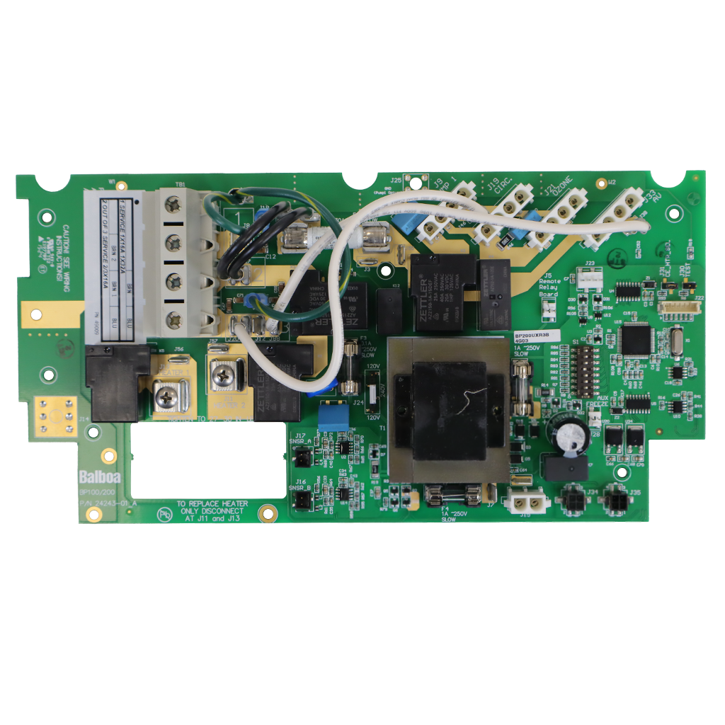
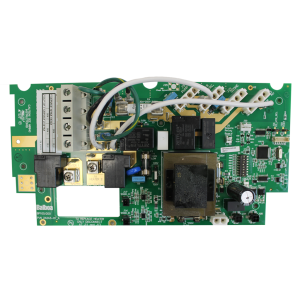
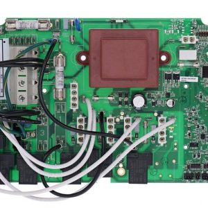
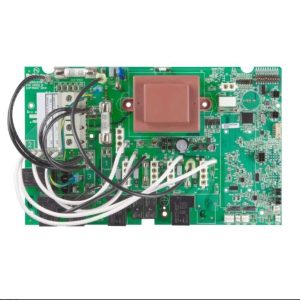
Balboa BP200UX 3.0kW Spa Circuit Board – BP200 Series Replacement PCB
£282.46 Inc VAT
15 in stock
🔌 Balboa BP200UX 3.0kW Spa Circuit Board – BP200 Series Replacement PCB
Restore full functionality to your spa with this genuine Balboa replacement circuit board.
📋 Product Overview
The Balboa BP200UX 3.0kW PCB is the main control circuit board for BP200 series spa packs, manufactured by Balboa Water Group. This circuit board serves as the central controller for your spa, managing pump operation, heating, lighting, ozone generation, and audio-visual equipment.
This PCB is designed as a combination of the BP200G1, BP200G2, and BP200G3 systems into one unified model. The board includes pre-installed mounting hardware for optional user-installed expander boards, allowing configuration from simple single-pump setups to multi-pump and blower configurations.
The BP200UX automatically detects 50Hz vs 60Hz power frequency and is specifically designed for CE (European) electrical standards at 230V AC.
✨ Key Features
✅ BP200 Series Replacement – Combination of BP200G1, BP200G2, and BP200G3 systems into one model
✅ 230V/50Hz European Standard – Designed for CE electrical standards with automatic 50/60Hz detection
✅ 3kW Heater Control – Integrated heater control up to 3.0kW @ 240VAC maximum
✅ Pump 1 Control – Single or dual-speed pump support, 12A maximum
✅ Optional Pump 2 – Single-speed 12A max (requires X-P2151 expander board, part 59233)
✅ Optional Blower – Single-speed 4A max (requires X-B expander board, part 59231)
✅ Circulation Pump Support – 2A maximum for 24hr filtration
✅ Ozone Generator Output – 0.5A maximum, slaved to heater pump
✅ Spa Light Control – 10VAC On/Off, 1A maximum, 240-minute timer
✅ A/V Output – 230VAC, 2A max, always on
✅ WiFi Ready – Designed for use with WiFi transceiver (sold separately)
✅ Pre-installed Expander Mounting – Hardware pre-installed for optional expander boards
✅ CE Certified – CE System Model: BP2-BP200UX-RCA-3.0KW
🔧 Technical Specifications
| Specification | Value |
|---|---|
| Part Number (800 Incoloy) | 59340-02 |
| Part Number (825 Incoloy) | 59371-01 |
| Part Number (Titanium) | 59381-01 |
| Replacement Main PCBA | 59507 (for 3.0kW models) |
| Board Type | Main PCB / Control Board |
| Input Voltage | 230V AC |
| Frequency | 50/60Hz (automatic detection) |
| Single Service (1×16A) | 16A, Circuit Breaker 20A max |
| Single Service (1×32A) | 32A, Circuit Breaker 40A max |
| 2-out-of-3 Service | 2/3 phase × 16A, 20A breaker each phase |
| Heater Output | 3.0kW @ 240VAC max |
| Pump 1 Output | 12A max (single or dual-speed) |
| Pump 2 Output | 12A max single-speed (requires X-P2151) |
| Circulation Pump | 2A max |
| Blower Output | 4A max (requires X-B expander) |
| Ozone Output | 0.5A max |
| Light Output | 10V AC @ 1A max |
| A/V Output | 230V AC, 2A max (always on) |
| Software Version | M100_235 V52.0 |
| CE System Model | BP2-BP200UX-RCA-3.0KW |
| WiFi Compatibility | Yes (module sold separately) |
| Expander Support | Pre-installed mounting hardware |
🔗 Compatibility Guide
Compatible Topside Control Panels
| Panel Model | Minimum Version | bba/bba2 Support |
|---|---|---|
| spaTouch 2 | Any version | Version 2.0+ for bba2 fully integrated |
| Icon spaTouch | Any version | Version 3.36+ for bba2 fully integrated |
| Menued spaTouch | Any version | Version 2.8+ for bba integrated |
| TP800 | Version 3.1+ | Version 3.13+ for bba; Version 4.11+ for bba2 |
| TP600 | Version 2.7+ | Version 2.12+ for bba/bba2 On/Off via menu |
| TP500 | Any version | bba/bba2 via “BT” menu entry |
| TP400T CE | Version 2.7+ | Version 2.12+ for bba/bba2 On/Off via menu |
| TP400W CE | Version 2.7+ | Version 2.12+ for bba/bba2 On/Off via menu |
⚠️ Important: TP400T US and TP400W US should NOT be used with this CE system.
⚠️ Note: DIP Switch A7 must be OFF when using graphic panels (TP800, TP900, or spaTouch family).
Replaces Previous Systems
This board is a combination of:
| Previous System | Status |
|---|---|
| BP200G1 | Replaced by BP200UX |
| BP200G2 | Replaced by BP200UX |
| BP200G3 | Replaced by BP200UX |
Replacement Parts
| Part | Part Number | Description |
|---|---|---|
| Main PCBA (3kW) | 59507 | Replacement circuit board for 3.0kW models |
| Main PCBA (2kW) | 59508 | Replacement circuit board for 2.0kW models |
| Expander X-P2151 | 59233 | For Pump 2 (Setups 1 & 2) |
| Expander X-B | 59231 | For Blower (Setups 3 & 4) |
⚙️ Board Functions & Controls
Setup Configurations
The BP200UX supports seven pre-programmed configurations. System ships configured in Setup 5.
| Setup | Circ Pump | Pump 1 | Pump 2 | Blower | User-Installed Expander |
|---|---|---|---|---|---|
| 1 | Programmable Filtration + Polling | 1-Speed | 1-Speed | None | X-P2151 (PN 59233) |
| 2 | None | 2-Speed | 1-Speed | None | X-P2151 (PN 59233) |
| 3 | Programmable Filtration + Polling | 1-Speed | None | 1-Speed | X-B (PN 59231) |
| 4 | None | 2-Speed | None | 1-Speed | X-B (PN 59231) |
| 5 | Programmable Filtration + Polling | 1-Speed | None | None | None |
| 6 | None | 2-Speed | None | None | None |
| 7 | Programmable Filtration + Polling | None | None | None | None |
System Outputs
| Output | Voltage | Rating | Timer |
|---|---|---|---|
| Pump 1 | 230VAC | 12A max (1 or 2-speed) | 15-minute; 30-min for P1 Low in non-circ Setups 2, 4 & 6 |
| Pump 2 | 230VAC | 12A max (1-speed) | 15-minute |
| Blower | 230VAC | 4A max (1-speed) | 15-minute |
| Circ Pump | 230VAC | 2A max (1-speed) | Programmable Filtration + Polling |
| Ozone | 230VAC | 0.5A max | Slaved to Circ Pump (circ setups) or Pump 1 Low (non-circ setups) |
| Spa Light | 10VAC | 1A max | 240-minute |
| A/V (Stereo) | 230VAC | 2A max | Always on |
| Heater | – | 3.0kW @ 240VAC max | – |
Temperature Settings
| Setting | Default | Range |
|---|---|---|
| Temperature Display | °C | °C or °F |
| Hi-Range Min Set Temp | 80°F (27°C) | 50°F to 80°F |
| Hi-Range Max Set Temp | 104°F (40°C) | 60°F to 104°F |
| Hi-Range Default Temp | 100°F (38°C) | 50°F to 104°F |
| Lo-Range Min Set Temp | 50°F (10°C) | 50°F to 80°F |
| Lo-Range Max Set Temp | 99°F (37°C) | 60°F to 99°F |
| Lo-Range Default Temp | 70°F (21°C) | 50°F to 99°F |
| Freeze Threshold | 44°F (7°C) | In Setups 1 & 2 |
🛠️ Installation Requirements
⚠️ IMPORTANT: Installation must be carried out by a qualified electrician in accordance with UK electrical regulations.
Electrical Requirements
| Requirement | Specification |
|---|---|
| Supply Voltage | 230VAC |
| Frequency | 50/60Hz (auto-detect) |
| Single Service (1×16A) | 3 wires (line, neutral, ground), 20A breaker max |
| Single Service (1×32A) | 3 wires (line, neutral, ground), 40A breaker max |
| 2-out-of-3 Service | 4 wires (line 1, line 2, neutral, ground), 20A breaker each phase |
| Conductor Type | Copper conductors only |
| Conductor Rating | Sized on 60°C ampacity, rated minimum 90°C |
⚠️ IMPORTANT: Service must include a neutral wire, with a line to neutral voltage of 230VAC. 3-phase service measured line-to-line will read about 400V, but BP systems do not use it line-to-line.
Key Connector Locations
| Connector | Function | Rating |
|---|---|---|
| TB1 | Mains power input | Torque: 27-30 in.lbs |
| J9 | Pump 1 (1/2-speed) | 12A max |
| J19 | Circulation pump | 2A max |
| J21 | Ozone generator | 0.5A max |
| J15 | Spa light | 10V @ 1A max |
| J33 | TV/AV | 2A max |
| J11 & J13 | Heater sensors (Sensor A & B) | – |
| J34 / J35 | TP panels / WiFi transceiver | – |
Jumper Settings
| Jumper | Setting | Purpose |
|---|---|---|
| J31 | On 2 pins | For 3.0kW or higher heater (factory default for 3kW models) |
| J31 | On 1 pin | For 2.0kW or smaller heater |
| J44 | Centre two pins (240V) | Must be set for CE systems |
| J109 | Not applicable | For CE models |
⚠️ Warning: Setting DIP switches or jumpers incorrectly may cause abnormal system behaviour and/or damage to system components.
Heater Connection
| Specification | Value |
|---|---|
| Torque for heater connections | 30 to 35 in.lbs |
⚠️ Safety Warnings
Electrical Safety
⚠️ ALWAYS disconnect power before any work
⚠️ Installation by qualified electrician ONLY
⚠️ Connect only to circuits protected by a Class A GFCI
⚠️ A disconnecting means must be installed within sight from the equipment and at least 5 feet (152cm) from the spa
⚠️ Use copper conductors only
⚠️ Total output amp draw not to exceed max input rating of spa
⚠️ Use earth ground connections as indicated inside system enclosure
HiPot Testing Note
⚠️ Disconnect slip terminal with green wires from J6 prior to performing HiPot test. Failure to disconnect may cause a false failure of the test. Reconnect terminal to J6 after successful completion of HiPot test.
🔧 DIP Switch Configuration
Fixed-Function DIP Switches (S1)
| Switch | ON Position | OFF Position |
|---|---|---|
| A1 | Test Mode | Normal operation (normally OFF) |
| A2 | Add one high-speed pump (or blower) with Heater | Don’t add 1 HS pump with heater |
| A3 | Add two high-speed pumps (or 1 HS Pump and Blower) with Heater | Don’t add 2 HS pumps with heater |
| A5 | Special Amperage Rule B | Special Amperage Rule A |
| A6 | Memory reset | Store settings (set to OFF upon final installation) |
Note: A2 and A3 work in combination. Both ON allows heater to operate with up to 3 high-speed pumps running. A2/A3 all OFF = No heat with any high-speed pump or blower.
Assignable DIP Switches
| Switch | ON Position | OFF Position |
|---|---|---|
| A4 | 5-minute cooldown (Cooling Time B – gas heaters) | 1-minute cooldown (Cooling Time A – electric heaters) |
| A7 | Simplified Menus on TP400/TP500/TP600 | Regular Menus (compatible with all panels) |
| A8 | 3-Phase Special Amperage Rule enabled | 3-Phase Special Amperage Rule disabled |
⚠️ Important: Switch A7 MUST be OFF when using graphic panels (TP800, TP900, or spaTouch family). Switch A7 should be OFF if using WiFi, since WiFi doesn’t support Simplified Menus.
🔍 Test Mode & Setup Change
Accessing Test Mode
While the system is running, move DIP Switch 1 (A1) on S1 to ON. The system will enter Test Mode. The temperature display will show “T” after it instead of °F or °C.
Moving DIP Switch 1 to OFF will exit Test Mode.
⚠️ DANGER! HIGH VOLTAGE WILL BE ACCESSIBLE! SERVICE TECHNICIAN ONLY!
Display During Priming Mode
When the panel displays “RUN PMPS PURG AIR”, press any Temperature button ONCE to exit Priming Mode. You should see “—T” where the T indicates the system is in Test Mode.
📊 Fuses
| Part Number | Amperage | Location |
|---|---|---|
| 30136 | 30A | F6 |
| 26983 | 1A | F4, F5 on main board |
| 24514 | 0.1A | F3 |
| 24517 | 15A | F5 on X-P2151 expander (Pump 2 in Setup 1 or 2) |
| 30122 | 10A | F5 on X-B expander (Blower in Setup 3 or 4) |
🎯 Ideal Applications
| Application | Suitability | Notes |
|---|---|---|
| ♨️ Hot tubs with BP200 spa packs | Ideal | For BP200G1, G2, G3, or BP200UX systems |
| ♨️ Spas requiring 3kW heating | Suitable | Maximum heater output 3.0kW |
| ♨️ Single or dual-pump configurations | Suitable | Setups 5 & 6 (single), Setups 1 & 2 (dual with expander) |
| ♨️ Systems with blower | Suitable | Setups 3 & 4 (with X-B expander) |
❓ Frequently Asked Questions
Q: How do I know if this board fits my spa?
A: Check your existing circuit board for a BP200G1, BP200G2, BP200G3, or BP200UX marking. This PCB (part 59507) is the replacement main PCBA for all 3.0kW BP200 series models.
Q: Is this an OEM board?
A: Yes. This is a genuine Balboa Water Group circuit board.
Q: Do I need a qualified electrician to install this?
A: Yes. UK Building Regulations require hot tub electrical work to be carried out by a competent person.
Q: Will my existing topside panel work with this board?
A: The BP200UX is compatible with Balboa spaTouch panels, TP800, TP600, TP500, TP400T CE, and TP400W CE. Check the minimum software versions in the compatibility section. US versions of TP400 should NOT be used.
Q: What is the J31 jumper for?
A: J31 configures the board for different heater sizes. For 3kW heaters, place the jumper on 2 pins. For 2kW or smaller heaters, move the jumper to 1 pin only.
Q: Can I add a second pump or blower?
A: Yes, with the appropriate expander board. Use X-P2151 (part 59233) for a second pump in Setups 1 & 2, or X-B (part 59231) for a blower in Setups 3 & 4.
Q: What expander fuse do I need?
A: For Pump 2 (X-P2151): 15A fuse (part 24517). For Blower (X-B): 10A fuse (part 30122).
📥 Downloads & Resources
📄 BP200UX Technical Specification Sheet (PDF) – Official Balboa wiring diagrams, DIP switch configurations, setup instructions, and panel configurations
🏆 Why Choose the Balboa BP200UX 3.0kW PCB
✅ Genuine Balboa OEM – Manufactured by Balboa Water Group
✅ Universal BP200 Replacement – Combines BP200G1, G2, and G3 into one board
✅ CE Certified – Full compliance with European electrical safety standards
✅ Seven Configuration Setups – Flexible options to match your spa equipment
✅ WiFi Ready – Compatible with Balboa WiFi transceiver
✅ Comprehensive Documentation – Full tech sheet with wiring diagrams available
✅ Expander Board Support – Pre-installed mounting hardware for expansion
🤝 Why Buy from Parts4Tubs
✅ UK-based company with local customer support
✅ Fast UK delivery from Northamptonshire
✅ Expert technical advice from spa specialists
✅ Competitive pricing on genuine Balboa parts
✅ Warranty support available
✅ Returns within 30 days
✅ Help identifying the correct replacement board
⭐ Summary
The Balboa BP200UX 3.0kW PCB (part 59507) is the genuine OEM replacement circuit board for BP200G1, G2, and G3 spa control systems. Featuring 230V/50Hz CE compatibility, 3kW heater control, support for single or dual-speed Pump 1 at 12A max, optional Pump 2 or blower with expander boards, and compatibility with Balboa TP series and spaTouch topside panels. Order from Parts4Tubs for fast UK delivery and technical support.
Related products
Control Boxes, Spa Packs & Topside Controls
Control Boxes, Spa Packs & Topside Controls

Printed Circuit Board (PCB)
Control Boxes, Spa Packs & Topside Controls
Control Boxes, Spa Packs & Topside Controls
Control Boxes, Spa Packs & Topside Controls
Control Boxes, Spa Packs & Topside Controls